1 / 2

Basic Information
| Item | Specification |
| Product Model | Example: S11-M-500/10, S13-R-1000/20, S15-H-2500/35 (S=Three-Phase; 11/13/15=Efficiency Class; M/R/H=Structural Type; Capacity kVA/HV kV) |
| Rated Capacity | 30kVA~5000kVA (ONAN: 100% rated capacity; ODAF: 130%; ODWF: 160%) |
| Phase/Frequency | Three-Phase (standard); 50Hz/60Hz (±1% tolerance, customizable for 400Hz special use) |
| Connection Group | Dyn11 (default for distribution), Yd11 (for power transformer); Yyn0 (optional) |
| Cooling Type | ONAN (Oil Natural Air Natural) / ODAF (Oil Directed Air Forced) / ODWF (Oil Directed Water Forced) |
Operating & Environmental Conditions
| Parameter | Details |
| Ambient Temperature | -25℃~40℃ (standard); -40℃~45℃ (low-temperature/high-temperature models with modified oil). |
| Altitude | ≤1000m (derate 5% at 1500m, 10% at 3000m, 15% at 4000m). |
| Humidity | ≤90% @25℃ (no condensation); ≤50% @40℃. |
| Seismic Resistance | GB 50260-2013 / IEC 60076-11, 7-degree intensity (0.15g acceleration); 8-degree optional. |
| Protection Class | IP23 (outdoor, dust/rainproof) / IP20 (indoor). |
Losses & Impedance (Typical Values)
| Efficiency Class | Parameter | 500kVA/10kV Example | Test Condition |
| S11 (IEC IE1) | No-Load Loss (Po) | ≤810W | Rated voltage/frequency |
| Load Loss (Pk) | ≤5200W | Rated current, 75℃ | |
| S13 (IEC IE2) | No-Load Loss (Po) | ≤650W (20% lower than S11) | Rated voltage/frequency |
| Load Loss (Pk) | ≤4800W | Rated current, 75℃ | |
| S15 (IEC IE3) | No-Load Loss (Po) | ≤520W (36% lower than S11) | Rated voltage/frequency |
| Load Loss (Pk) | ≤4500W | Rated current, 75℃ | |
| All Classes | Short-Circuit Impedance (Uk%) | 4%~6% (10kV); 6%~8% (35kV) | 75℃, ±10% tolerance |
| No-Load Current (Io%) | ≤1.0% (30~250kVA); ≤0.6% (≥315kVA) | Rated voltage |
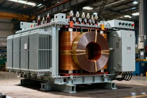
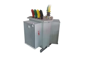
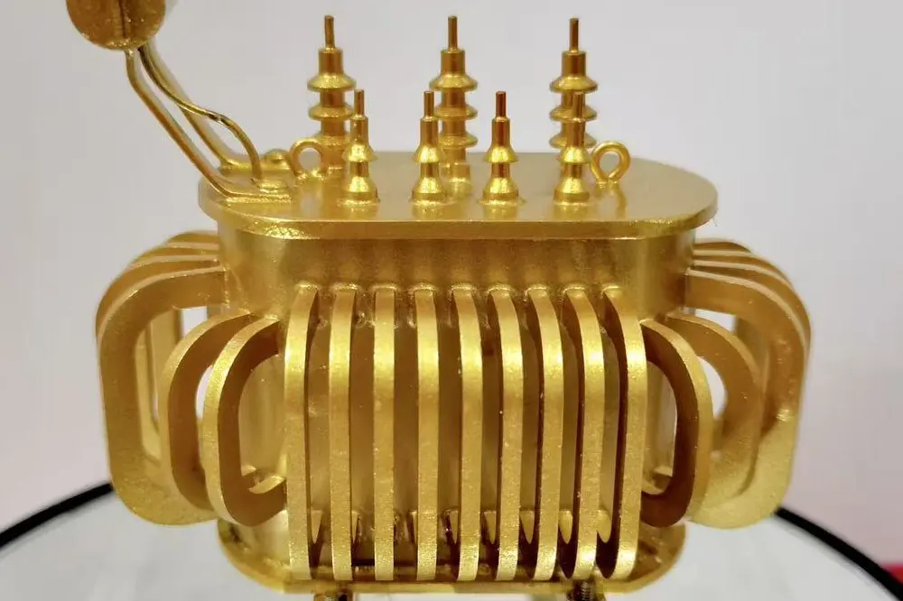
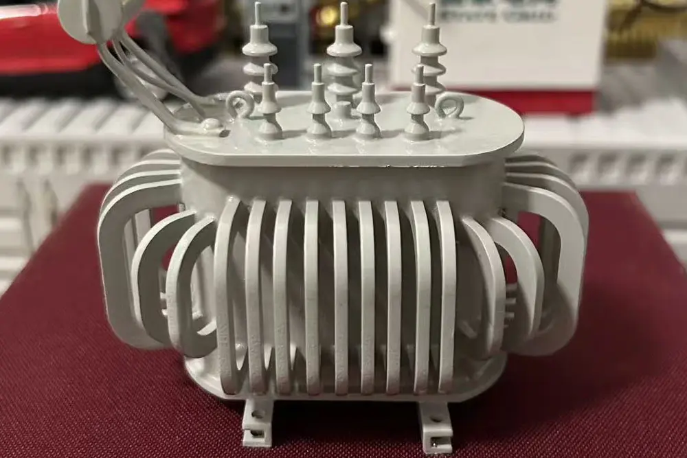
Leveraging high thermal conductivity of insulating oil, the transformer efficiently transfers heat to radiators, enabling stable operation under high loads.
Insulating oil isolates moisture and dust, reducing leakage risks and ensuring reliability in harsh industrial environments.
Optimized structure withstands short-term surges in production or peak use, minimizing performance degradation.
Sealed tanks protect components from corrosion. Design life typically exceeds 20 years, reducing replacement frequency.
Sealed structure reduces exposure to contaminants, simplifying operations and cutting long-term costs.
Widely used in power grids and infrastructure, meeting strict resistance standards for high-power transmission.
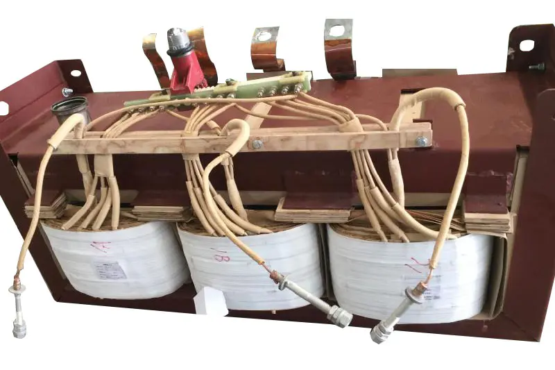
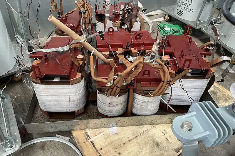
Indispensable for voltage conversion in regional power grids and substations, stepping down high-voltage power for industrial and residential use.
Powers high-capacity equipment in steel mills and chemical plants. Also serves as step-up transformers for new energy integration.
Ensures continuous power for critical services in hospitals, airports, and data centers where stability is paramount.
Robust sealed designs protect against humidity and corrosion in remote or hazardous mining and oilfield sites.